« Previous Next »

Air Data Sensor

Technical Information

Catalogue No: C1548
Category: Air Data
Object Type: Sensor/Transducer
Object Name: Air Data Sensor
Part No: 81-03-01
Serial No: 058/66
Manufacturer: Elliott
Division: Unknown
Platform(s): BAC 1-11
Year of Manufacture: circa 1965
Dimensions: Width (mm): 120
Height (mm): 190
Depth (mm): 550
Weight (g): 6,720
Location: Rack RAA10 [Main Store]
Inscription(s):

Elliott
Air Data Sensor
Type No 81-03-01
Ser No. 058/66

Mod Record Label 0,1,2,3,5,7,8.

Notes:

This is similar to the box made for the VC10 and has a Pitot and Static probe connection which suggests that it contains the usual electro-mechanical system involving the Elliott diaphragm and gears. The output will be parameters such as Airspeed and Altitude.

Air data systems provide accurate information on quantities such as pressure altitude, vertical speed, calibrated airspeed, true airspeed, Mach number, static air temperature and air density ratio. This information is essential for the pilot to fly the aircraft safely and is also required by a number of key avionic subsystems which enable the pilot to carry out the mission. It is thus one of the key avionic systems in its own right and forms part of the essential core of avionic sub systems required in all modern aircraft, civil or military.

The air data quantities; pressure, altitude, vertical speed, calibrated airspeed, true airspeed, Mach number etc. are derived from three basic measurements by sensors connected to probes which measure:

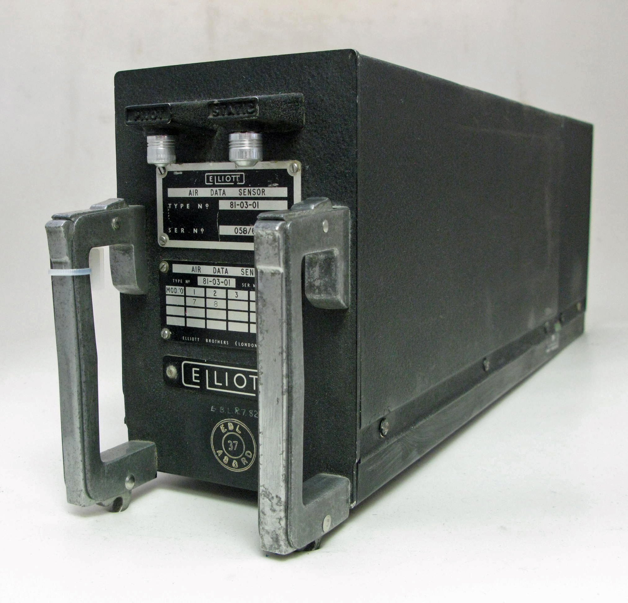
Total (or Pitot) pressure
Static pressure
Total (or indicated) air temperature

The total pressure, PT, is measured by means of an absolute pressure sensor (or transducer) connected to a Pitot tube facing the moving airstream. The Pitot pressure is a measure of ram air pressure (the air pressure created by vehicle motion or the air ramming into the tube). When airspeed increases, the ram air pressure is increased, which can be translated by the airspeed indicator.

The static pressure of the free airstream, PS, is measured by an absolute pressure transducer connected to a suitable orifice located where the surface pressure is nearly the same as the pressure of the surrounding atmosphere. The static pressure is obtained through a static port which most often is a flush-mounted hole on the fuselage of an aircraft located where it can access the air flow in a relatively undisturbed area. Some aircraft may have a single static port, while others may have more than one. When the aircraft climbs, static pressure will decrease.

High performance military aircraft generally have a combined Pitot/static probe which extends out in front of the aircraft so as to be as far away as practicable from aerodynamic interference effects and shock waves generated by the aircraft structure. A Pitot-static tube effectively integrates the static ports into the Pitot probe. It incorporates a second coaxial tube (or tubes) with pressure sampling holes on the sides of the probe, outside the direct airflow, to measure the static pressure. Some civil transport aircraft have Pitot probes with separate static pressure orifices located in the fuselage generally somewhere between the nose and the wing.

From the measurements of static pressure PT and total pressure PS it is possible to derive the Pressure Altitude, Vertical Speed, Calibrated Airspeed and Mach number. Measurement of the air temperature is made by means of a temperature sensor installed in a probe in the airstream and from this a function called Total Air Temperature can be calculated.

The BAC 1-11 AFCS, like that in the VC10, was based on the well proven Bendix PB-20 Autopilot and was designated the Series 2000 AFCS. New features over the PB-20 system include separate pitch and azimuth control computers, a modular Air Data Sensor and a range of units specifically designed for autoflare and autolanding.

Each unit in the BAC 1-11 AFCS is built to a common configuration with circuit modules arranged in stacks either side of the chassis. The stacks are connected by plugs to a mother board and are physically separated into ‘command’ and ‘monitor’ functions to preclude common failures. The computers are entirely solid state and there is a high degree of built-in-test. Self-monitoring techniques and multiple channel redundancy are used to give automatic failure survival in approach and cruise flight.

The basic requirement for an automatic landing is that the equipment must survive a single failure and continue to operate. Fundamentally, this can be achieved by triplication of all equipment. But in providing and justifying redundant equipment in civil passenger aircraft, consideration must be given not only to overall safety, reliability and performance, but also to weight, installation difficulties, overall cost, maintenance problems and many other factors. Unnecessary redundancy must therefore be avoided.

It is essential that effective autopilot disconnection should occur in the event of a failure and that the pilot should be warned of the failure and the control runs automatically freed. The disconnection and warning unit can only be electrical and must be made truly fail-safe. In practice, failure of the system to disconnect following an autopilot failure will occur only if both the autopilot and the disconnection device fail. The likelihood of this is remote as it involves a product of small probabilities in the landing phase. The acceptance of an electrically actuated disconnect device permits further simplifications of the duplicate channel, with an increase in system reliability and a saving in weight.

The operation can be checked in a different way by comparing the demand of the second autopilot with the effective demand of the first which is obtained by suitably processing the actual control output with the approximate inverse transfer function of the servo motor control loop. This concept is called a "monitored-duplicate" system and is the design used by Elliotts on the VC10. The comparison concept is used throughout the Autopilot and the Flight Director system with the various flight parameters derived in a stand-alone units. Because the duplicate sensors are used for comparison and not for actual control, they can be considerably simplified and therefore made more reliable and lighter than those used in the autopilot; and the inherent differences make them less liable to fail from a common environmental cause.

Longitudinal and Lateral Computers have equivalent Comparison computers, the Vertical Gyro has a simple comparison unit and the Air Data Computer core elements are separated for this purpose. Not all the functional boxes are compared in this way; in some cases such as the Polar Path Compass the units are duplicated and are compared electro-mechanically but there is not a Comparison unit.

Click to enlarge Click to enlarge