« Previous Next »

Vertical Gyro

Technical Information

Catalogue No: C1153
Category: Gyro
Object Type: Sensor/Transducer
Object Name: Vertical Gyro
Part No: 15866-2C
Serial No: 102104
Manufacturer: Bendix
Division: Eclipse-Pioneer [of Bendix]
Platform(s): BAC 1-11 , VC10
Year of Manufacture: circa 1968
Dimensions: Width (mm): 210
Height (mm): 220
Depth (mm): 210
Weight (g): 6,660
Location: Rack RAA09 [Main Store]
Inscription(s):

Vertical Gyro
115V 400cps Single Phase
Type No. 15866-2C
Patent No. 2,890,430
TSO-C4c S.A.E. AS396B
TSO-C9b S.A.E. AS402
TSO-C52 S.A.E. AS420
Wt. lbs. 15
Serial No. 102104
The Bendix Corporation
Eclipse-Pioneer Div.
Teterboro, New Jersey
Made in U.S.A.
──────────────────
Modification Record
5, 12, 15, 23 & 26

Notes:

The Vertical Gyro was supplied by Bendix and was an electrically driven gyro forming the main vertical reference for the autopilot. In addition to providing pitch and roll attitude information, it also provides a signal which is used to give ‘up elevator’ during turns. The Vertical Gyro has an interlock switch to prevent autopilot engagement before the gyro has run up. A second Comparison Vertical Gyro was incorporated in the system to monitor the output from the main gyro.
This unit bears the maintenance marks:
"EBL.R. Jan 97"
"6TK6577358"
and the inspection stamp:
"GMAv S.D(R) 118"

The given weight includes its two 720mm cables.

From the early days of the company it had been hoped to enter the civil aircraft flight control field, in order to reduce dependence on military projects. The late 1950s was a time of significant change in the automatic flight control field. Elliott made a major contribution to this evolution by the design and development of actuation systems which integrated the electronic control input with the hydraulics of the main flying control power actuator.

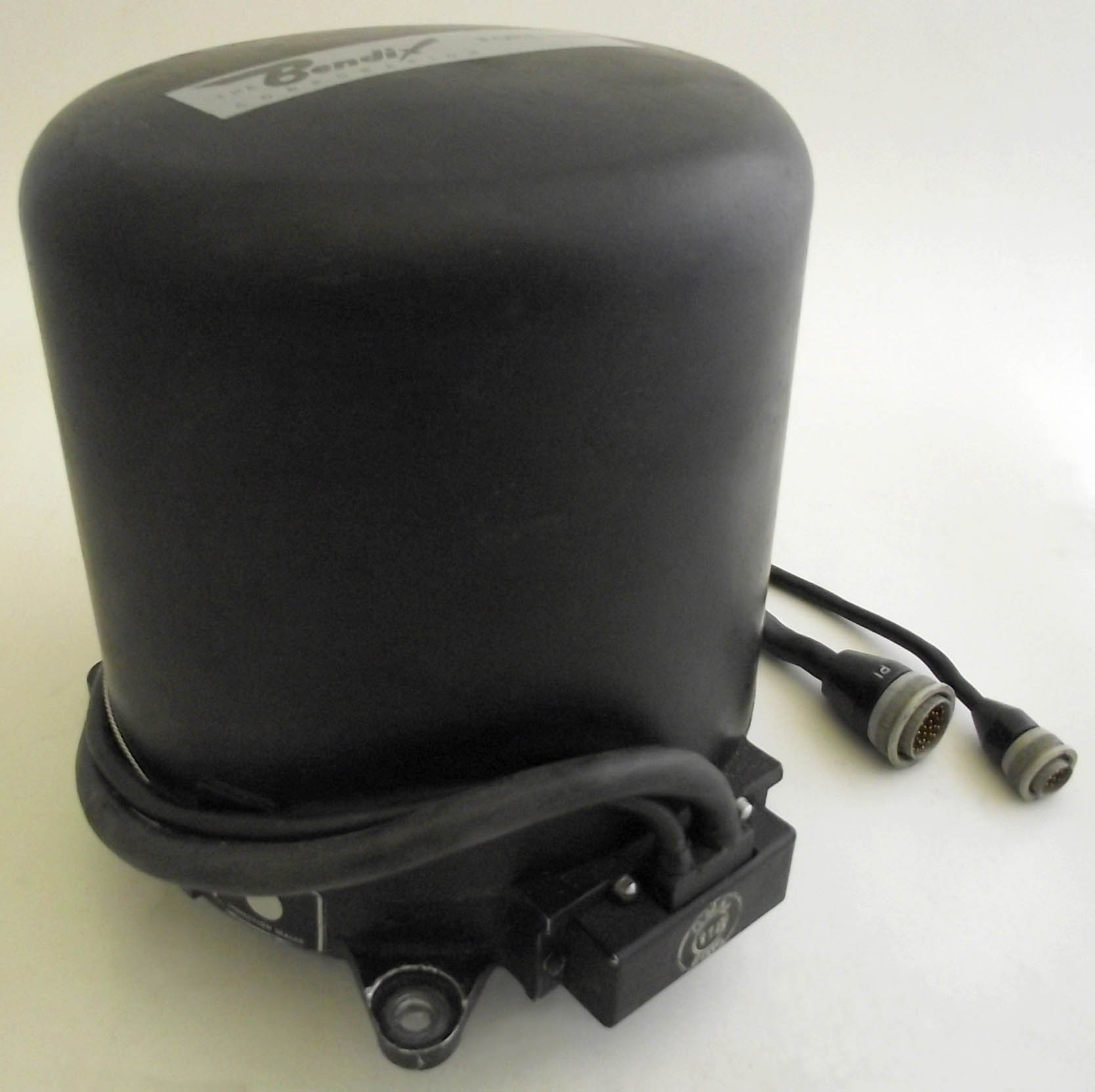
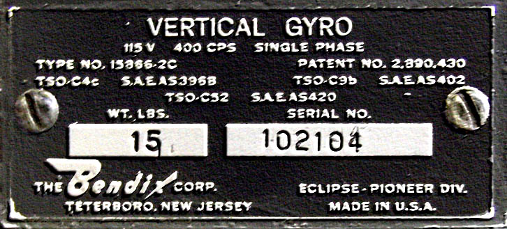
The opportunity to take this step came in the late 1950’s with the planning of the Vickers 'VC 10' for which Elliott Brothers secured an order to provide a complete automatic flight control system. This led to considerable shared responsibility with the airframe designs of the Vickers VC 10, where the main control surfaces were split into several separate units. From the outset, the 'VC 10' system was planned to make provision for fully automatic landing of the aircraft. For certification ever to be possible an extremely high standard of reliability was essential, and even in the case of failure of the equipment it was a requirement that the aircraft must not be subjected to violent manoeuvres. After a detailed study of possible alternatives, the solution chosen was to duplicate the whole of the major system, one half to be operative while the other was to be 'standing by', with a changeover mechanism of the utmost reliability to permit instant switching from one to another. By 1960 the basic development was substantially complete and the requirements for automatic landing were being explored in detail with full 'autoland' capability available from January 1963. Successful development of the 'VC 10' system resulted in the opportunity to supply broadly similar equipment for the British Aircraft Corporation 'BAC 111', which has been produced in substantial numbers. The automatic flight control system of the Standard and Super VC10 was designed to be capable of development to full blind landing. To meet this requirement the system had to be capable of failure survival and this includes associated services such as power supplies and flying controls. The method of autopilot failure survival chosen was to provide two monitored systems which are fail soft, i.e. there is negligible aircraft disturbance after a failure. Only one autopilot is used to fly the aircraft, and the two systems, including power supplies, are completely independent. Each autopilot has a comparison monitor which detects faults and, in flight, will disconnect the system if these faults are likely to lead to dangerous conditions. For autoflare the system provides for automatic changeover to the second monitored autopilot system, in the event of fault in the first. Under these conditions the second autopilot is primed and ready to take over. If for any reason the monitoring system fails to prevent an autopilot runaway, the control movement is limited to a safe amount by the yielding of a torque-limiting spring. Many of the needed components were already present in the autopilot fit on the Standard VC10s, to achieve the autoland capacity the system on the Super received some additional items. The system, supplied by Elliott Brothers (London) Ltd, was based largely on components of the well-proved Bendix PB-20 autopilot, made under licence by Elliott, and interchangeable with American built components as installed in Boeing 707s. However, the system as a whole i.e., the dual autopilot concept was novel, and designed entirely by Elliott.           

A comprehensive description of the VC10 systems will be found at this VC10 website.


The BAC 1-11 AFCS, like that in the VC10, was based on the well proven Bendix PB-20 Autopilot and was designated the Series 2000 AFCS. New features over the PB-20 system include separate pitch and azimuth control computers, a modular Air Data Sensor and a range of units specifically designed for autoflare and autolanding.

Each unit in the BAC 1-11 AFCS is built to a common configuration with circuit modules arranged in stacks either side of the chassis. The stacks are connected by plugs to a mother board and are physically separated into ‘command’ and ‘monitor’ functions to preclude common failures. The computers are entirely solid state and there is a high degree of built-in-test. Self-monitoring techniques and multiple channel redundancy are used to give automatic failure survival in approach and cruise flight.

The basic requirement for an automatic landing is that the equipment must survive a single failure and continue to operate. Fundamentally, this can be achieved by triplication of all equipment. But in providing and justifying redundant equipment in civil passenger aircraft, consideration must be given not only to overall safety, reliability and performance, but also to weight, installation difficulties, overall cost, maintenance problems and many other factors. Unnecessary redundancy must therefore be avoided.

It is essential that effective autopilot disconnection should occur in the event of a failure and that the pilot should be warned of the failure and the control runs automatically freed. The disconnection and warning unit can only be electrical and must be made truly fail-safe. In practice, failure of the system to disconnect following an autopilot failure will occur only if both the autopilot and the disconnection device fail. The likelihood of this is remote as it involves a product of small probabilities in the landing phase. The acceptance of an electrically actuated disconnect device permits further simplifications of the duplicate channel, with an increase in system reliability and a saving in weight.

The operation can be checked in a different way by comparing the demand of the second autopilot with the effective demand of the first which is obtained by suitably processing the actual control output with the approximate inverse transfer function of the servo motor control loop. This concept is called a "monitored-duplicate" system and is the design used by Elliotts on the VC10. The comparison concept is used throughout the Autopilot and the Flight Director system with the various flight parameters derived in a stand-alone units. Because the duplicate sensors are used for comparison and not for actual control, they can be considerably simplified and therefore made more reliable and lighter than those used in the autopilot; and the inherent differences make them less liable to fail from a common environmental cause.

Longitudinal and Lateral Computers have equivalent Comparison computers, the Vertical Gyro has a simple comparison unit and the Air Data Computer core elements are separated for this purpose. Not all the functional boxes are compared in this way; in some cases such as the Polar Path Compass the units are duplicated and are compared electro-mechanically but there is not a Comparison unit.

Click to enlarge Click to enlarge