« Previous Next »

C-17 HUD CRT Assembly

Technical Information

Catalogue No: C0426
Category: Head-Up Display [HUD]
Object Type: Module/Sub-Assembly/Component
Object Name: C-17 HUD CRT Assembly
Part No: G0906-S6-3
Serial No: 103883
Manufacturer: Rank Electronic Tubes
Division: Unknown
Platform(s): C-17 Globemaster
Year of Manufacture: 1996
Dimensions: Width (mm): 114
Height (mm): 114
Depth (mm): 210
Weight (g): 1,003
Location: Cupboard CA (CRTs) [Main Store]
Inscription(s):

Rank Brimar
Type No: G0906-S6-3
Serial No: 103883
Part No: K06560CN9002-00046
NSN:
Date Code: 9634H
NSCM. U3008
Made in England

Notes:

This Cathode Ray Tube does not have its Matching Card to make it a Tube Unit Assembly. The Matching Card would normally be fitted by Rank Electronic Tubes. The Part No. is 9002-00046 which the reference data gives as a TUA for the Eurofighter Typhoon but also states a top level number of 79-108 which is definitely the C-17.

In August 1984 Stafford Ellis invented a slimline optical system which involved placing a prism in the middle of the optical path in order to reduce the height of the Pilot’s Display Unit. 

 In 1985 the Company commenced the design of a HUD with the patented shallow optical relay. A few HUD's were built for the US Navy A-6 but this order did not materialise however a variant of the design was used for the HUD for the C-17 transport. The Request for Proposal was sent to Pilkington Electro-Optical Division in June 1985. An attachment to this RFQ from Dave Steward shows how difficult the design was to achieve the customer’s procurement specification with the space constraints of the HUD envelope, over nose line and windshield clearance. The top lens element had to be modified from the planned single element because of unacceptable coma and chromatic aberrations. Although the optics is fairly conventional the HUD achieves a Total FoV of 30deg x 24deg with an instantaneous Field of View in the C-17 of 25deg in azimuth and 22deg in elevation. This shallow optical design allows the HUD to be mounted on the cockpit coaming although the penalty is that the prism is heavy; the all up weight of the unit is 54lbs and the prism block is expensive. The dual Combiner assembly has neutral density coatings but has 80% transmission and the coatings are graded to transfer the image between the two glasses. Unusually the Combiner assembly folds down flat onto the exit lens housing to allow cross cockpit visibility. The parallel motion mechanism was patented as it has to collapse both glasses and when they are restored a very high accuracy must be reproduced and performance maintained over the environment.

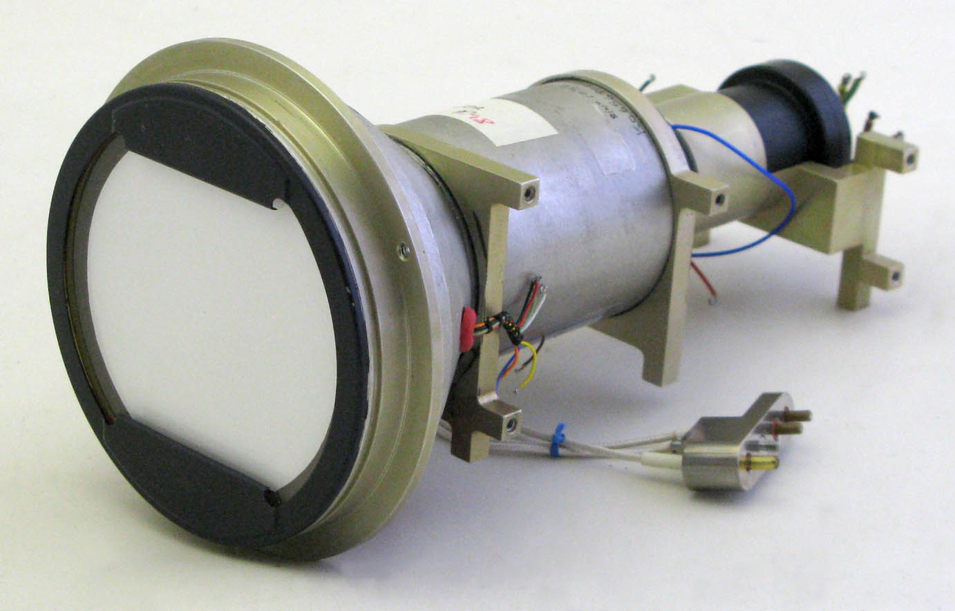
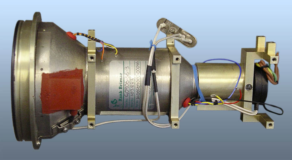
The HUD for the C-17 was claimed to be the world's first HUD designed as a critical flight instrument. With the ever-increasing miniaturisation of circuit devices: hybrids and ASICs, it was feasible to construct a HUD with twin integral MIL-STD-1750A processors, the 1553B interface and waveform generator in a single box, the electronics being built into the optical unit rather than being separate. Parallel processing is used to feed back the commanded deflections to compare them to the input and this in part achieves an integrity of 10^(-6) critical failures per hour (i.e. one failure per million hours). Another feature of the single Line Replaceable Unit is that it is air cooled even though the power consumption is only around 100W. Most HUDs are fitted into a tray which has mechanical adjustments to align the unit to the aircraft axes but there is sufficient adjustment on the deflection system and CRT to permit electronic boresighting. Finally, the C-17 HUD was designed to allow growth to display raster video from EO sensors with flight symbology overwritten in stroke.

The more recent Cathode Ray Tube (CRT) for the Company Pilot’s Display Units are supplied as a CRT Assembly incorporating the CRT within its mu-metal housing. The CRT has a deflection coil within the casing which magnetically deflects the beam; focussing is electrostatic. The final anode operates at a high voltage of 18kV or more and the focus voltage is in the range 3-5kV.
A range of fine grain phosphors are used on the screen and the inside face, on which the phosphor is deposited, is accurately aligned to the mounting flange of the tube to ensure it coincides with the optical module's image plane.
When the CRT Assembly is fitted with its Matching Card it forms a Tube Unit Assembly (TUA).
The latest raster/cursive CRTs have a blank or silvered area usually at the bottom of the screen where the beam is deflected for a beam current calibration test. This is found on F-16 C/D (which introduced the idea), LANTIRN and Typhoon.

4500 Series GEC Ferranti HUD: This TUA operates in a raster or cursive mode and uses a P43 phosphor.
C-17 HUD: The circular faceplate of this CRT is blanked top and bottom to match the shallow prism optics in the relay. A P43 phosphor is used and the HUD was planned to have growth to a raster display but this was not installed. This part number in the reference database is wrongly attributed to EFA.
F-5 HUD: This is a conventional TUA and is cursive mode only with a P1 phosphor
F16A/B HUD: It was during this programme that the TUA became a subcontract item. The cursive only TUA uses a P1 phosphor
F-16C/D HUD: A large circular screen with a test area and using a P1 phosphor The TUA operates in raster/cursive and combined modes. 
Gulfstream HUD: A truncated CRT operating in cursive modes with a P43 phosphor
LANTIRN HUD: A truncated CRT operating in raster/cursive and combined modes with a P43 phosphor
Typhoon HUD: A truncated CRT operating in raster/cursive and combined modes with a high drive P53 phosphor

Click to enlarge Click to enlarge