« Previous Next »

HUD Video Camera Electronics Unit

Technical Information

Catalogue No: C0813
Category: Head-Up Display [HUD]
Object Type: Signal/Data Processor
Object Name: HUD Video Camera Electronics Unit
Part No: 1291C1
Serial No: 1529A
Manufacturer: Fairchild Weston
Division: Unknown
Platform(s): F-16A/B Fighting Falcon
Year of Manufacture: 1982
Dimensions: Width (mm): 188
Height (mm): 44
Depth (mm): 165
Weight (g): 962
Location: Rack RAA12 (collection part) [Mezzanine Store]
Inscription(s):

CTVS AN/AXQ-16(V)
Electronics Unit
SerNo 1529A
Mfr 55006
PN 1291C1
NSN 5821-01-093-4630
Conr F33657-79-C-0722
U.S.
────────────────
This item warranted for 365 days
Warranty terminates 22 Jun 1983
Process defective items under Para. 134, Sect. J, Chap.10, Part One, Vol. 1, AFM 67-1

Notes:

This is the Electronics Unit and base from a camera designed, built and tested to USAF requirements for use with the F-16A/B Head Up Display. The camera consists of a Video Sensor Head (VSH) assembly and an Electronics Unit (EU) assembly which can be separated up to 20 feet or directly coupled to provide a compact integral assembly. Input power for the Camera is obtained from the 115 VAC, three phase 400 Hz aircraft power source.
Five of these cameras were purchased by the USAF for the NASA-Johnson Space Center (JSC) under contract No, F33657-79-C-0722 to be used on the Space Shuttle Orbiter. For the NASA/JSC application, the cameras were modified to operate from a 28Vdc supply, a number of circuit changes were made, the normal 31 mm focal length lens assemblies were removed and replaced with wider field-of-view 19mm focal length lenses, and some mounting and heat sink arrangements were changed to suit the space environment.
The Contract date is 1979 but this Camera seems to have been supplied in 1982 with a one year warranty. Operational flights of the Space Shuttle began in 1982 and five complete Shuttle systems were built. It is understandable that one of these Cameras should be at Rochester because the F-16A/B HUD was supplied by the Company but the contract for NASA-JSC has no link to Rochester as far as is known although Marconi Avionics did bid for the Space Shuttle HUD but were unsuccessful.

In January 1972 the Lightweight Fighter Programme asked for designs from several American manufacturers. In January 1975 General Dynamics was pronounced the winner with the YF-16. Since its small beginning with an initial USAF order for 650 aircraft, the F-16 has become one of the largest and most successful military aircraft in aviation history. At least 23 countries have purchased the F-16 in various forms.

The HUD system, which at one point seems to have been called the HUDSIGHT by the Company, consisted of a Pilot’s Display Unit (PDU), an Electronics Unit (EU) and a Rate Sensor Unit (RSU).  General Dynamics however called it the Fire Control Sight System FCSS.                                                                                     

The F-16 A/B was an international programme with a requirement for offset. The HUD PDU and EU were both built in Rochester and at Atlanta in Georgia, de Oude Delft in the Netherlands also built the PDU and  Kongsberg Vapenfabrik in Norway also built the EU. The Rochester site was responsible for the design, production and supply of complete HUD systems. The legend "27489" on the Ident labels of many of the boxes is a defunct CAGE code for the Rochester site of Elliott Bros (London) Ltd.   

The PDU has four functional groups, the cathode ray tube assembly (CRT), the optical module, the chassis and the control panel. The CRT assembly comprises the tube itself, the deflection coils and a matching circuit to compensate for minor variations in individual CRT’s. The CRT was made by Rank Brimar and it was this system that initially used the Muirhead deflection coils.

The Total Field of View of the F-16 A/B PDU is 20deg but the Instantaneous FoV is only 9deg in elevation and 13.38deg in azimuth because the combiner to eye distance is quite large due to the highly angled seat. The whole optical system has to correct for display distortions and try to correct for canopy distortions. The F 16 bubble canopy is particularly difficult and every canopy is different needing unique correction. The lens system is a standard Petzval design but it includes a prism block used to inject a red Standby Sight. The Sight is depressible from a PDU Control Panel and has a Night Blind to reduce the intensity of the display at night. At this time it was not possible to get a very low and stable luminance on the CRT; there was always the danger that it might disappear altogether so the Night Blind allowed the tube to be run at a higher and stable luminance. The housing for the Standby Sight lamp gives a prominent finned bulge under the aft end of the PDU.

The PDU has a very rigid Combiner frame to withstand birdstrike on the F 16 where the canopy can deform onto the HUD and it is even possible for a bird to penetrate the canopy. These PDU’s are unique in being designed and tested to withstand both windblast if the canopy is lost and birdstrike.

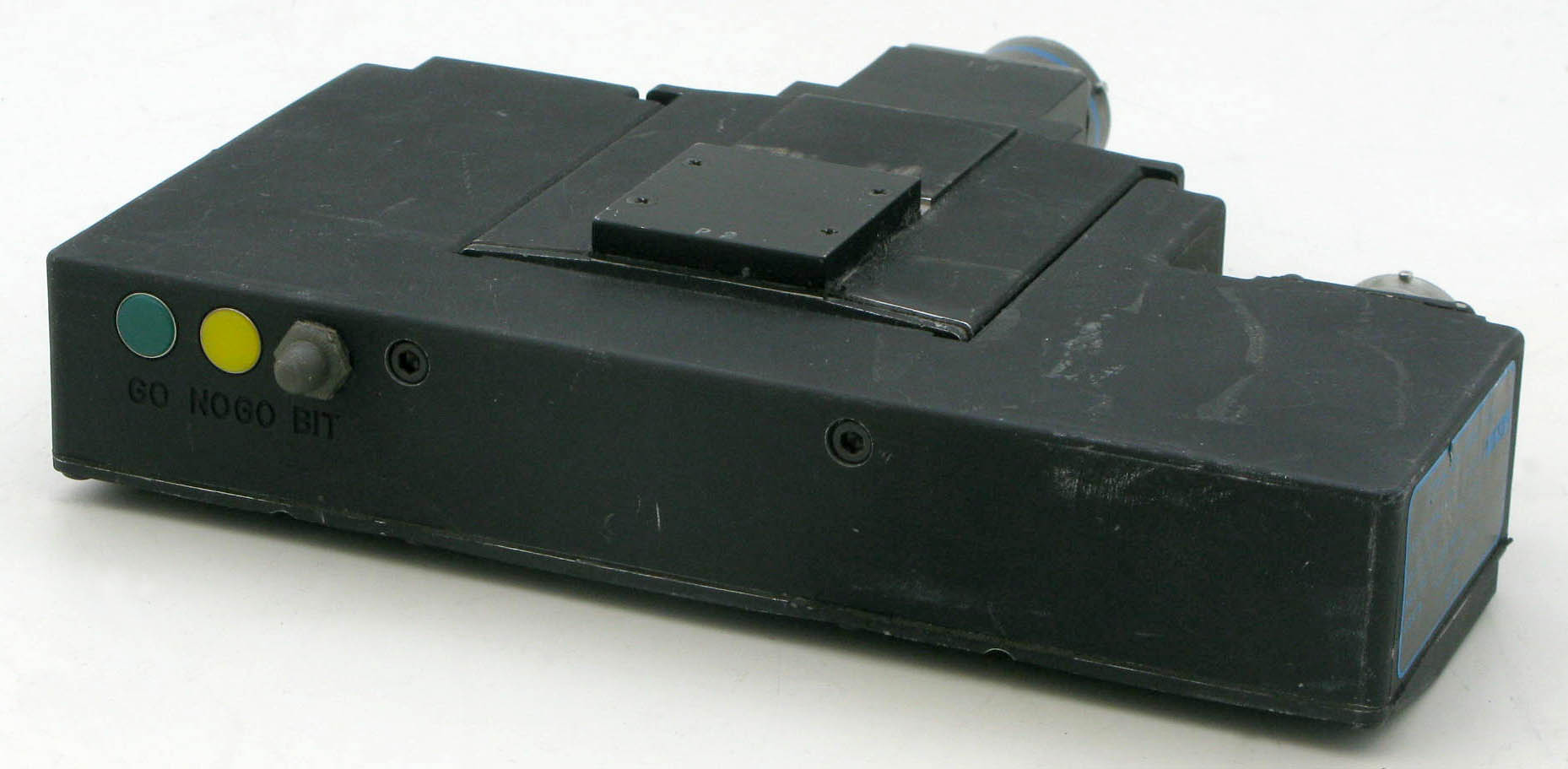
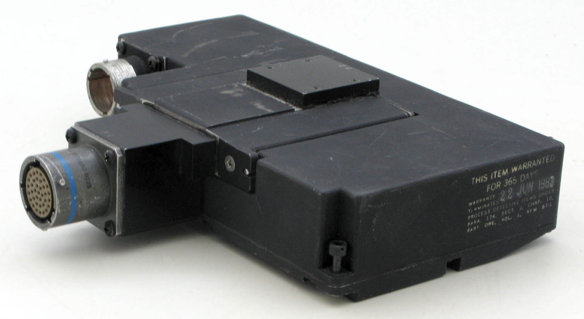
The F-16 Electronics Unit was based on a powerful general purpose computer using MSI TTL technology. It contains a MIL-STD-1553 data bus interface, processor and symbol generator. Data can be received in analogue form but the digital Databus significantly reduces the number of data lines. With progressively smaller airframes finding space for the traditional bundles of analogue cables and their bulky connectors was becoming a problem so the new system links HUD, attack radar, fire control computer and the inertial navigation system all through the 1553 data-bus. Development of small RISC processors had continued within ADD and FARL and the F-16A/B emerged with a solid state 16K 16-bit store in what was basically a 12/16 RISC implementation. Eventually the memory was increased to 32k.


A Camera is used with a Head Up Display to view the symbology overlaid on the outside world as close as possible to the view that the pilot has through the Combiner Glass. The Camera is a training aid to show how accurately the fighter aircraft engages with the target and ultimately can verify the result of a real engagement.

The Camera assembly is usually mounted on top of the HUD, above the Control Panel, directly aft of the Combiner Glass.

The earliest Cameras used film strip with a replaceable film module and these were quite large and obstructive to the pilot.  However with the advent of diffractive and waveguide optical systems the Combiner acts as part of the optical collimation and is not just a reflector so that the symbology is not focused at the normal location used.  A new solution had to be found and the Camera is instead located forward of the Combiner and the HUD symbology is scan converted and accurately mixed with the Camera video.

Fortunately solid state Cameras were developed, using a CCD chip which converts the optical image into electrical video signals for output to an on-board video recorder or transmitter. Solid state Cameras are also considerably smaller and more reliable.

The camera electronics incorporate extensive filtering to provide exceptional, noise-free, image quality. 

Click to enlarge Click to enlarge
Related Items: