In a cockpit of a transport aircraft there are two general areas in which a projection unit can be installed: the glareshield or the overhead area. The overhead area is generally preferred (the C-17 was a notable exception) but installation is bounded by the structure and pilot’s head clearance. In general, the space available reduces sharply going outboard and increases going inboard. Overhead switch panels and eyebrow windows often reduce the space available. Overhead Projection Units were developed by the Company for civil and business aircraft systems in conjunction with Honeywell. The system was known as the 2020 because of the obvious connection with good vision. In 1996 the 2020 design was reduced in size and this new system was called the 2022 HUD.
In 1997 American Airlines solicited replies to a Request For Proposal for a HUD in its Boeing 737-800 and the Company won this major order for 75 displays valued at over £120m. This was a significant breakthrough into a major new business area with the initial order extending to up to 400 extra 737s on which American Airlines held purchase rights, plus possible fitment in other types in the airline's fleet, such as the MD-80 and 757-200.
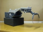
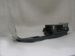
The system comprises the Overhead Unit, the Combiner Assembly and Control Panel, a Mounting Tray and a Drive Unit. The Overhead Unit contains the Optical Relay assembly the CRT and the electronics with an integral HV Power Supply. The optical system gives a large eye motion box of 20 x 15 x 7.5cms.
The system operates in a cursive or cursive on raster mode to permit the use of sensor video and the TFoV is 30deg x 24deg. Cat 3 Certification was gained in a record two years under the leadership of Brian Harris who coordinated the liaison with the FAA.
American Airlines retrofitted the VGS into 22 Boeing 737-800’s which have been delivered, plus another eight due for delivery over the next four months. All retrofits were carried, out at the rate of one a week, by Marconi Flight Systems at Mojave, California, where the flight tests were carried out. The balance of the fleet was equipped by Boeing at Renton, Washington, around the first quarter of 2000.
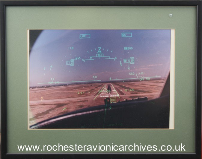
The HUD gives guidance in Take Off and Go-Around the HUD providing positive guidance and 'v' speed bugs which enable take off in reduced runway visual range conditions (RVR) down to 90m (300ft)
In Approach the HUD provides guidance from localizer capture right down to touchdown, including all the necessary annunciations from "outer marker" to "idle". The symbology auto-declutters at Cat III decision height. In Landing from Cat III decision height, the HUD provides guidance down to touchdown including a flare cue and engine idle prompt, Positive centreline rollout guidance is also provided.