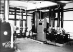
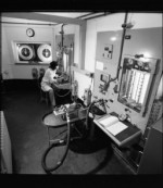
The Fuel flow business was important to Elliotts and a new fuel-flow test laboratory—the most advanced in Europe, if not in the world—was opened at Elliott-Automation's Rochester factory on November 20 1964 by Mr Neil Marten, Parliamentary Secretary to the MoA.
Enclosed in a blast-absorbing concrete emplacement, it was designed to test fuel flow equipment for the new generation of supersonic aircraft where fuel temperature of 150°C or higher would be encountered, and units would be required to operate at rigid standards of accuracy under extreme conditions of temperature (up to 200°C ambient) and in areas of extreme vibration.All controls and observers are in a separate building and several closed-circuit TV cameras give a view of critical parts of the system. Hot water and freon are used respectively as heating and cooling media. The laboratory is suitable for developing flow-measurement systems for supersonic airliners or VTOL aircraft.
The Laboratory can achieve gravimetric calibration accuracy within an error band of ±0.1% of flow rate under the following conditions:
1. Flow rates from 50 to 120,000 lb/hr through three different bores of pipe.
2. Fuel temperatures from -55°C to +180°C.
3. Ambient temperatures from -60°C to +200°C.
There is also a Vibrator capable of producing a maximum thrust of 500 pounds with frequencies of up to 3,000 c.p.s. for resonance searches.
Mass-flow test measurement is effected by weighing the fuel as it accumulates in a tank mounted on a weighing balance, the whole unit being housed in a sealed container filled with nitrogen.
Fuel measurement systems such as Tank capacity, Fuel Flow rate, Fuel Remaining, Fuel Consumed were all big business for Elliott Bros (and subsequent names) and a snapshot of the platforms to which these were fitted can be gained from one of the Company databases:
AV8B, Buccaneer, Concorde, Dominie, EFA, Fiat Rig, Hawk, HS125, HS146 (BAe146), Javelin, Sea Venom, Sea Vixen, Valiant, Scimitar, P1127, Phantom, Phoenix, Trident, Transall C160, MRCA (Tornado), Finnish Hawk, G222, VC10, RB211 and RJ500 engines.........